

The problem: How to double-check that our load cell and logger are providing accurate data?
Our solution: A 20kg calibrated weight, a balanced lever and some low-friction bearings.
Timescale: Less than a day from concept to fully specified and verified design.
Throughout my career, I’ve always found the capability to accurately apply, measure and record load one of the most fundamentally useful capabilities in a composite engineer’s toolbox. Even a simple setup unlocks countless possibilities in terms of understanding materials performance, validating structures and answering questions that are impractical to address through analysis.
So it’s with significant excitement that we’re putting the finishing touches to the load test frame that will shortly play a central role in our composite materials R&D programme. Featuring hydraulic loading and rated to 100kN, our setup also boasts a bespoke PC interface that permits load data to be viewed in real time and logged to a datafile…….
…..all of which is great, as long it gives us the right answers! So it’s necessary in this case to conduct a full system validation: Our solution to this problem is to use a balanced lever to load up a 5kN load cell using a 20kg calibrated mass. Even though it’s a fairly simple problem, we’re pleased to have solved it and completed all the relevant design work within a day of putting pen to paper. For reasons of customer confidentiality, it’s not that often that we can show pictures of our efforts, so it’s also great to take opportunities to share as they arise!
Our starting point in this case was to sketch out the idea and put a few simple numbers to our scribbles: Key geometry, loads & reactions and a quick check of critical stresses. None of this takes long but it ensures that we don’t waste time when we dive into the computer!
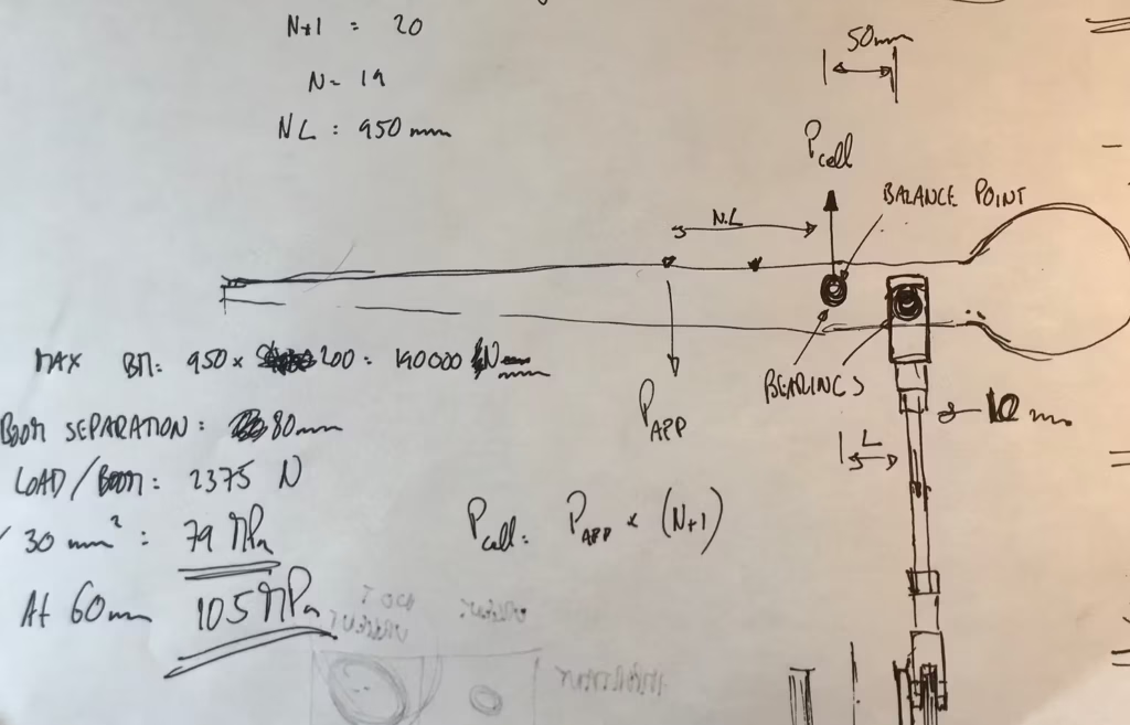
Are we heading in the right direction? Never underestimate the power of a quick sketch and some simple hand-calcs!
The next stage was to select the necessary off-the-shelf hardware (clevises, bearings etc.) and to generate the geometry of the critical arm component in CAD. As our Nastran FE integrates seamlessly with our CAD software, it was a really quick job to double-check preliminary stress predictions (happily correct!) and also run a buckling analysis.
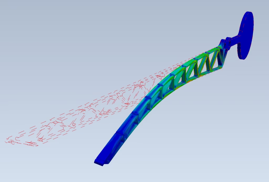
Buckling check
Having successfully met all the relevant criteria, it remained only to create the necessary part and assembly documentation. The bespoke parts are now out for quotation and we should have the hardware installed and operational in a week or so.
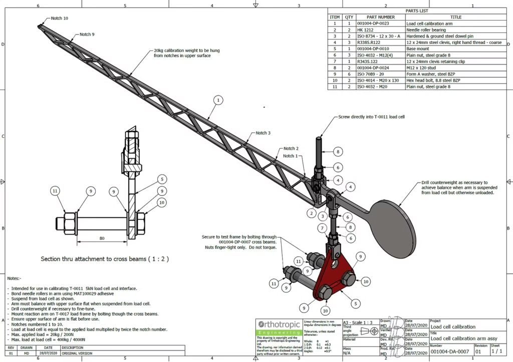
Assembly drawing
Please do get in touch if you’d like to discuss this or indeed any of our other capabilities or services.